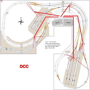
This weekend a start has been made feeding DCC to the track.
The challenge with wiring is to find your own personal preference in a mix of partly conflicting requirements. DCC voltage drop can be an issue. It’s a function of wire length, wire thickness and the current running through it. An easy solution is to use (overly) thick wires, but that would add unnecessary cost. Wire chaos can be another issue. There will be a lot of wiring under the table, DCC, accessory power, junction servo control, S88 sensor wiring. I think some sort of labeling system would be nice not to lose oversight.
What I liked to achieve is minimal cost (as usual 🙂 ), but still have a solution that works well (for me). These were my starting points:
– Use wires that are no thicker than needed.
– A wiring design that keeps wire lengths minimal.
– Minimal use of parts. There’s a wide range of wiring and connection aids on the market. They can be nice, or be handy, but they also add cost.
How many DCC rail connects would I need? Well … the layout has 23 junctions, with isolated rail joiners at the frog. That means a DCC feed is needed behind every junction. With a few additional feeds on long tracks, it added up to 26 connects, spread everywhere over the layout.
 For the wiring diagram I chose a ‘star’ network with 5 main branches (in stead of the more frequently used ‘DCC bus’ that mirrors the main tracks under the table).
With this star network, the wires that run the highest currents can be kept short. The longest one is just 1.8 m.
From each end node, 5 or 6 short sub branches feed the DCC to the rails.
 The first preparations: the 5 branch wires have been cut to length.
 This is the DCC center node. Max current will be less than 4 A (6 trains).
The wire from the Command Station to the center node is 2.5 mm². This is overkill, but I had some old speaker cable available :). It’s the grey wire.
The 5 main branches are 1 mm² wires, the black/red ones. Lengths vary between 1.0 – 1.8 m.
Max current per sub branch will be about 0.7 A (1 train). Wire thickness for these track feeds is 0.15 mm². Lengths vary between 0.3 and 1.0 m.
 Sticky tape is used to fix the wires. The tape is ‘3M Durapore’, also known as ‘nurse tape’, as it is frequently used in hospitals. It really sticks very well to any surface!
 It doubles as a labeling system. The track block numbers are written on the tape, or simply the word DCC, to distinguish form other wires.
 DCC has no polarity, it is an alternating block voltage. But ‘+’ and ‘-‘ must stay the same over the whole layout. I use this simple reminder: bLack = Left , Red = Right. But what is left en right on the track? With sports events on ovals, traffic is always counter-clockwise … that way I can remember.
The main 5 branch star is done. Next job: connect the 26 sub branches / track feeds. And then … well, I guess then it’s time for a test drive! Possibly with a video.

Je gaat lekker
hou je rekening met aftakpunten van je dcc signaal voor je arduino ?
ik las ook iets over een 5 volt netwerkje, dan zul je relatief snel last krijgen van spanningsverlies
denk eens na over een wisselspannings netwerk met lokale spannings regelaars
LikeLike
Posted by dick koning | March 9, 2015, 08:37O ja … de 3 servo-Arduinos moeten ook een aftakkinkje hebben! Ik heb nog wel een plekje op het dichtstbijzijnde kroonsteentje.
De 5V wordt ook een ster netwerk. Max lengte naar de te voeden punten is zo’n 2m en de stromen zijn niet groot. Denk dat het spanningsverlies dan wel meevalt. Praktijk moet het uitwijzen.
Bedankt voor het meedenken!
LikeLike
Posted by rudyb2014 | March 9, 2015, 11:07