rudysmodelrailway
Traincontroller Gold File including Graphics (October 2015)
 This is the download link for the TC Gold file, with the icons and backgrounds graphics. Please copy the yrrg file to the folder where you store your TC files. TC does not store background images inside the yrrg file. They can be placed in any folder and then double click the image icon (diagonal striped square) and tell TC where the image is stored.
The LCD is available in 4 colors, blue, orange, grey and green. The counters on the LCD screen have a comment that mentions the counter color used with each of the LCD colors.
Click the image to enlarge.
Arduino + ATtiny DCC Decoder / DCC Sniffer / S88 software download (October 2015)
Over time several types of the Arduino DCC decoder software have been made, such as accessory-, servo-, function-decoder, S88 interface, DCC sniffer, Sound software. All are available from now on in one overall zip download:
Arduino DCC, S88, and more Download link
 To convert the DCC track voltage to the Arduino voltage level, an optocoupler circuit is used according to the image on the right. Click the image to enlarge.
To find the various blog posts and video’s on the subject please do a search (upper right, in header) on the words arduino decoder.
Please visit the Arduino website for download and installation of the Arduino development environment, needed to use Arduino sketches (‘sketch’ is the name for an Arduino software app).
Unzip the file and you’ll find the following folders:
libraries
The folders inside need to be moved to the Arduino Sketches/libraries folder on your PC. All other folders go into your Arduino Sketches folder.
RB_RGB_LED_Control
Arduino sketch to control max 6 PWM channels that can control a 12V LED strip via nMOSFET’s. User manual desrcibing the needed hardware and how to configure the software is included.
RB_DCC_Decoder_Function
Arduino sketch for a one address function decoder with max 13 outputs, controlled via the F0 – F12 buttons on your Command Station or handheld controller. More info on this post. Configuration is very straightforward:
int decoderAddress = 1830; // This is the decoder address, change into the number you want.
#define F0_pin 13 // Define the output pin for every Function number in use. 13 has on board LED.
#define F1_pin 0 // Available pin numbers: 3-19
#define F2_pin 0
…
#define F12_pin 0
RB_DCC_Decoder_Function_ATtiny
ATtiny sketch for a one address function decoder with max 5 outputs, controlled via the F0 – F12 buttons on your Command Station or handheld controller. More info, see above.
RB_DCC_Decoder_Accessory
Arduino sketch for DCC control of accessories. More info is available here. Configuration per output:
accessory[0].address = 1; // DCC address
accessory[0].mode = 1; // Continuous: HIGH until DCC switches the address off again
accessory[0].outputPin = 10; // Arduino pin to which this function is connected
accessory[1].address = 2;
accessory[1].mode = 2; // Oneshot: HIGH for ontime ms, then LOW and stays LOW.
accessory[1].outputPin = 11;
accessory[1].ontime = 1000;
accessory[3].address = 3;
accessory[3].mode = 3; // Flasher: HIGH for ontime ms, LOW for offtime ms, repeats till DCC off
accessory[3].outputPin = 12;
accessory[3].outputPin2 = 13; // Flasher can use 2 outputs, they will flash on/off alternatively
accessory[3].ontime = 500;
accessory[3].offtime = 1000;
RB_DCC_Decoder_Accessory_ATtiny
ATtiny sketch for DCC control of accessories. Configuration is identical to the Arduino version above.
See this post for more info on installation of drives and ATtiny support for the Arduino IDE.
RB_DCC_Decoder_Servo
Arduino sketch for DCC control of servos. Click here for a list of posts on the servo decoder.
Configuration per servo:
servos[0].address = 1; // DCC address for this accessory
servos[0].outputPin = 13; // Arduino pin number for additional accessory output
servos[0].servo.attach(3); //Arduino pin number where servo is connected to
servos[0].offangle = 68; //Angle for DCC=off
servos[0].onangle = 126; //Angle for DCC=on
RB_DCC_Decoder_Servo_Tune_v3.0
Very basic sketch that I use to tune the servo’s min and max angles to switch a turnout. The workings are explained inside the software. Here are a few video’s. Min / Max values are displayed on screen and then need to be manually configured in the DCC_Servo sketch.
RB_DCC_Decoder_Solenoid
Version of the accessory decoder sketch that can be used to switch turnouts that use two coils for switching. Some additional hardware is needed to power the coils, the Arduino outputs do not deliver enough current for that. Configuration:
accessory[0].address = 1; // DCC address for this accessory
accessory[0].durationMilli = 250; //Duration of pulse in ms
accessory[0].outputPin = 12; //solenoid 1 connection
accessory[0].outputPin2 = 13; // solenoid 2 connection
RB_DCC_Decoder_Sound
Arduino sketch on DCC control of playing sounds. For use with the Sound Software that also is included in the download. This version only plays sounds, has no accessory or servo functions, just to make it simple to use. More info here.
RB_DCC_Decoder_Accessory_Servo_Sound_Delay
Arduino sketch that combines ‘all in one’ control of accessories and servo’s and can play sounds using the additional PC sound software. There’s also a delay function, that makes it possible to delay an output. Useful for instance with a railway crossing: first the 2 lights start blinking (2 output flasher function) and the ding-ding sound starts to play, then some time later the servo moves the beams down.
More info here.
Sound_Software (For MS Windows PC’s only)
Software to install on the PC that works together with the Arduino DCC_Decoder_Sound sketch to play sounds, triggered by DCC.
Sounds
Some sample sounds for use with the DCC_Decoder_Sound and the Sound Software.
DCCSound_User_Manual.doc
Detailed description how to install and to use the Sound Software and the DCC_Decoder_Sound.
RB_S88
Arduino sketch for connection of track sensors to an S88 bus and transmit their data to a command station or PC.
See this post for more info
Arduino used as a 16-sensor S88 detector board (September 2014)
 I’d like to see if an Arduino can be used as an S88 16x detector board. Why? Well … for one it is just a fun challenge to see if we can get that to work. And next, more interesting, an S88 board sets you back some €40,- … an Arduino just some €6,- !
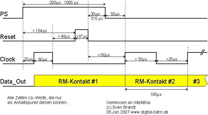 The S88 interface is a shift register with the timing diagram as shown in the image (info from this website). The ECoS sends out the “PS” and ‘Clock’ signals and reads the data line. I did some measurements on the ECoS. It sends out 512 clock pulses between the PS signals, which means it always reads the maximum of 32×16 detector inputs. With that knowledge I started work on the Arduino hardware and software.
Software:
The Arduino code can be downloaded here: Arduino s88 interface sketch.
The main loop scans all 16 inputs and stores the state in a 16 bit integer called ‘sensors’. Upon receipt of the PS pulse interrupt-1 is triggered, in which ‘servos’ is copied into an integer called ‘data’, after which ‘servos’ is reset to zero. Every ‘Clock’ pulse triggers Interrupt-0, which sequentially sends out the 16 bits from ‘data’ to the ‘dataOut’ pin, using a modulo 16 counter. After sending each bit it reads the data-in, to which the data-out of the next Arduino in the chain is connected. This way all sensors up to max 512 are sent to the Command Station.
Connections:
 The wiring between ECoS and Arduino, looking at the S88 connector, from left to right:
S88 pin – Arduino pin
1 data – 13 (dataOut and LED indicator)
2 GND – GND
3 Clock – 2 ( =interrupt 0)
4 PS – 3 (=interrupt 1)
5 Reset – not used
6 Vcc – 5V
not conn – 12 (dataIn)
Arduino pin 12 is used for ‘data-in’. If more than one Arduino is used, they can be ‘chained’ by connecting the data-out pin 13 of the next Arduino to the data-in pin 12 of the previous Arduino. The first one in the chain has data out pin 13 connected to S88.
For the sensors anything can be used that pulls an Arduino input to GND, like a reed switch or an optical detector. I wanted to try the TRCT5000. See the hardware page for details. However … I changed to using reed switches and little magnets under the rolling stock. See this blog post for a video on that. The reason is that the IR sensors are too sensitive to surrounding light.
Videos:
See this blog post for a video that shows the Arduino S88 board in action, initially with just one Arduino and max 16 inputs.
And see this blog post for a video that shows the final version of the software, with miltiple Arduino’s in ‘chain’.
ECoS screen on PC / tablet / smartphone via a VNC client
(Sep 2014) ECoS firmware 4 has a VNC server built in, which makes it possible to not only show the ECoS screen on your PC or tablet, but also to operate it! A very nice feature.
One could use the Internet browser and connect to the ECoS IP address. To get VNC to work Java Runtime Edition (JRE) needs to be installed and some Java security settings need to be modified. It’s all in the video mentione below.
In stead of using the web browser, the way I prefer is to use a VNC client on the PC, simply because it looks better. RealVNC has a viewer that has a small footprint. It does not even need an insall, just create a shortcut to the file and run it. Works very nice, with scalable window and some other options..
VNC clients are also available (for free) for tablets and smart phones. On the iPad I tried several. The one I liked best is the Mocha VNC Lite viewer.
See this post for a video on the connection and the use of the VNC server / client.
Connect ECoS to JMRI
(Aug 2014) See this blog post.
Connect ECoS to PaHaSoft Koploper
(Aug 2014) See this blog post.
Connect ECoS to Rocrail
(Aug 2014) See this blog post.
Software I use:
(Aug 2014) For model rail layout CAD: SCARM. It’s free and it’s easy to use.
For model railway simulation: Railroad-X , or actually I use the German version Eisenbahn-X. It’s the best model railway simulator I know, although opinions always differ of course.
For railraod control I intend to try out:
Traincontroller This is the software I currently use for layout control (Gold version). Many video’s are available on this blog on its use.
Rocrail
Koploper (a Dutch program, no English translation)
JMRI (Java Model Railroad Interface)
iTrain
All are free software (iTrain is free with limitations, 3 types of licences are available fom €79,- onwards)
Discussion
149 thoughts on “Software”
Trackbacks/Pingbacks
-
Pingback: - April 22, 2021

$4 dcc generator — youtube demo —-> https://www.youtube.com/watch?v=NSRU2ZYB_7U source in the description
LikeLike
Posted by sonnycruz | April 22, 2021, 02:46Hi Rudy,
Allereerst complimenten voor jouw site en de duidelijke youtube tutorials
Ik heb al enkele jaren al mijn wissels aangestuurd d.m.v. Arduino en servo’s volgens de methode en schakeling die ik van jouw site heb overgenomen. Dit werkt prima. Alleen heb ik nu iets heel erg vreemds. Ik weet niet bij wie ik voor zo’n vraag terecht terecht kan misschien zeg het jouw iets of kan je aangeven in welke richting ik moet zoeken. Het is ook niet echt een probleem. omdat het op de ene manier wel werkt en op de andere niet.
Ik had een oudere Uhlenbrock IB op mijn buro (werkplek). De railspanning loopt via een kabel van ongeveer 2 a 3 meter naar de treintafel, waar deze wordt afgetakt voor de rails en alle elektronica die een DCC signaal behoeven. Op de werkplek heb ik ook een proefopstelling met Arduino, servo en relais. Dit werkte OK. Nu heb ik de Uhlenbrock vervangen door een Digikeijs DR5000. Geen enkel probleem behalve dat de proefopstelling niet meer werkt. Na van alles geprobeerd te hebben, heb ik als laatste de Rail spanning niet direct vanaf de DR5000 gehaald, maar met een tijdelijke kabel van onder de treintafel. Hiermee werkte de proefopstelling weer. Daarna weer aan dezelfde kabel maar dichterbij de DR5000 en de proefopstelling werkte weer niet. Dit wel meer dan tien keer geprobeerd. Kabel dicht bij de DR5000 alleen wat brommen van de servo. Kabel onder de tafel aangesloten en het werkt perfect. Voor mij lijkt dit op tovenarij. 100% zeker is het dezelfde kabel, alleen op een andere plaats afgetakt. Ook de testopstelling van het buro gehaald en op diverse plaatsen weggezet. (straling???) Het blijft echter altijd hetzelfde . Aansluiting dicht bij DR5000 werkt niet. Verder weg wel. Het enige probleem is dus dat ik niet kan uitstaan dat ik het niet kan verklaren. Idee???
Met vriendelijke groet,
Gino
LikeLike
Posted by Gino Siemerink | January 20, 2021, 15:29Dit soort storingen is vaak afkomstig van elektromagnetische straling. Niet te verklaren hoe en waar die door de ruimte lopen. Bij een vriend die een berglandschap aangehouden is wilde twee servo’s op hoogte niet werken, alsmaar storing. Ik ontdekte als ik se 15cm lager vasthield ze wel goed werkten … maar ja, ze moesten op die berg. Soms kunnen ontstorings condensatoren helpen. We hebben extra condensatoren op de voeding gezet, zo dicht mogelijk bij de servo’s en … ze werken! Bij jou klinkt het ook als storing, heel subtiel. De DR5000 zendt wellicht wat meer elektromagnetische ‘troep’ de ether in, misschien ook omdat het een WiFi zender is. Je zou eens extra condensatoren op de voeding kunnen testen. Vaak is een combinatie van een 20-100 uF elco samen met een 100nF ontstorings Ctje de uitkomst.
LikeLike
Posted by RudyB | January 20, 2021, 15:39Bedankt voor het snelle antwoord. Ik ga dit proberen. Krijg ik het opgelost zal ik dat nog posten.
LikeLike
Posted by Gino Siemerink | January 20, 2021, 21:41Combinatie van 100 uF elco en 100NF ontstoringscondensator heeft inderdaad geholpen. Bedankt. Geen problemen meer 🙂
LikeLike
Posted by Gino Siemerink | July 30, 2021, 21:47Hi Rudy,
I came accross your traincontroller tutorials.
I am interested in the layout of the icons and backgrounds graphics you have used . The link above to the download seems not working anymore. Is ther an other way to get the download?
ALso your android projects are very interesting.
LikeLike
Posted by Volker | December 9, 2020, 08:42Hi Rudy,
What software do you use to create your video tutorials ?
Thank You
J-F
LikeLike
Posted by JF | November 18, 2020, 08:40NCH Debut Video Capture.
LikeLike
Posted by RudyB | November 18, 2020, 09:16Dear Ruud
I could load the DCC Function Decoder Sketch into an ATtiny 85 without any problem. The ATtiny is correctly connected via 6N137. I use DCC++ and get no reaction. The internal clock is set to 1 MHZ. Must I set an other value for the clock or other parameters ?
Best regards
Josef
LikeLike
Posted by Josef Zinkernagel | September 7, 2020, 18:09The internal clock of what? DCC is a protocol that uses pulse width measurement to distinguish between 0 and 1 and this must be done with enough accuracy. With an Arduino clock of 16MHz the pulse measurement accuracy is 4us, which is just enough. Slower clocks will make it less accurate and could mess up the readings. It could also be a hardware issue.
LikeLike
Posted by RudyB | September 8, 2020, 08:23Good morning, Rudy.
Very many thanks for your fantastic site – you projects are really useful and very well explained.
I am very interested in using the sound/server/lights sketch but would like to use a separate speaker to play the sound, located in a signal box on the layout.
If you have the time and the interest, would you consider doing a project write-up for the sound sketch but using for a MP3 module (which seem to be cheaply available) and speaker connection for the output that could be mounted on the layout to play sounds, rather than use a PC.
Very many thanks,
Pete
LikeLike
Posted by Pete Ross | August 5, 2020, 08:32Pete, I’m sorry but I don’t have the time for that at the moment … too busy with all kinds of other stuff.
LikeLike
Posted by RudyB | August 5, 2020, 09:11Rudy,
Thank you for sharing your knowledge and patience, I’m a fan of DCC and since I’m already retired this Covid 19 made me revive my dcc interest. I made a youtube video of my dcc board (in Tagalog) link below. Thank you for your inspiration and sharing your source code. I enjoy more the electronic side of dcc than running a layout 🙂 The youtube description shows a link to a dropbox for all the source code including yours.
Salamat,
Sonny
LikeLike
Posted by sonny | July 17, 2020, 22:30Looks nice! Have fun with it.
LikeLike
Posted by RudyB | July 18, 2020, 09:51Hi Rudy, many thanks for your help in trying to solve this shuttle problem in TC I’m having. Feel free to email me and I’ll happily send you further details.
LikeLike
Posted by Christopher Jacobson | July 16, 2020, 13:58Hello Rudy,
Thanks for all Arduino projects again! I have an issue about how can create a DCC Decoder Function with sound effects, using a little mp3 player ( DF Player mini mp3). Unfortunatelly to comunicate from Arduino to DFPlayer I need to use serial comunication ( SoftwareSerial.h ), but these libraries are in conflict with the DCC libraries ( DCC_Decoder.h ) and dosn’t work! I seen your RB_DDC_Decoder_Sound, but I want create a Decoder Sound function without PC!
Did you just have same issue? When you have time, please try to help me….. 😉
LikeLike
Posted by Mauro Bianchi | March 14, 2020, 11:15I’d get a second Arduino to connect the MP3 player to. The DCC Arduino can send digital outputs, connected to the MP3 Arduino’s inputs to determine which sound to play.
LikeLike
Posted by RudyB | March 14, 2020, 14:32Hi Rudy,
I have watched your YouTube footage on the Arduino amongst many other videos with great interest – they are great, however before I embark on purchasing any hardware I wondered if you would be kind enough to suggest the best solution to my conundrum.
I am in the process of restoring a signal box panel that came out of a signal box in 1986. It has 25 blocks and each block is illuminated by 2 x 12vDC 0.1A light bulbs in parallel. I have connected these to a bank of solid state relays that require a voltage between 3.3 and 5vDC 160mA. I am using a Digikeijs DR5000 Command Station with DR5088RC feedback detectors as I wish to show upto four loco ID’s per block that the DR5088RC captures from RailCom and transmit it back through loconet. As for the computer software, I am currently undecided on whether to use iTrains, Train Controller or Rocrail. I have tried multiple block occupancy with iTrains and it works fine, but I feel that the iTrains software is not as well endowed with functionality as the Train Controller software; have you tried multiple loco occupancy with these other software packages? from what I can gather it will be the computer software that will trigger the signal for the panel blocks to illuminate, possibly via an Arduino, or could the code be written in DrScript on the DR5000 that can trigger the panel block lights? I am open to your suggestions.
Kindest Regards and thank you for being such an ambassador to our hobby.
Darren Tecklenberg (UK)
LikeLike
Posted by Darren Tecklenberg | February 10, 2020, 19:41I have only done multiple locs in a block with TC but only with 2 locs. You need 4, I have no experience with that. My guess is that as long as you have enough detectors per block to detect every train it could work. The best advice I can give is to download TC and try it.
Yes, the PC software can be used to switch the relays, via a DCC decoder, for which I would use DCCNext (www.arcomora.com) which set you back just €7,50 for 16 DCC controlled outputs.
LikeLike
Posted by RudyB | February 13, 2020, 12:50Hallo Rudy,
i have S88 arduino nano board with digikeijs DR5000 and your S88 Software.
The signal comes correct, when I grounded an input.
The problem is, the neighbor bits are jitter!.
Connected is over RJ45 cat 5.
What can I do? Please help me.
LikeLike
Posted by Otto Wehrheim | February 5, 2020, 11:18What helped with me to suppress flickering is to connect all unused inputs to GND and particularly pin 12 of the final Arduino in the chain. It’s the input where the next Arduino should be connected to, but if it is the final in the chain there is no next. What might also help is to tune the delay timing that is somewhere in the code.
LikeLike
Posted by RudyB | February 6, 2020, 10:34Hoi Rudy,
heb je pagina ontdekt en het werkt super.
Alleen zit ik met het versturen van info naar een DISPLAY die I2C protocol heeft.
Ik lees ergens in de commentaren dat de opdrachten naar de dcchandler moeten, en niet in de loop kunnen, klopt dat?
Ik snap dat met die Interrupts nog niet zo.
groeten
Bert
LikeLike
Posted by Bert | January 10, 2020, 10:53Over welke sketch heb je het Bert? Klopt het I2C adres van het display?
LikeLike
Posted by RudyB | January 10, 2020, 14:47Ik gebruik DCC_Decoder.h en jouw voorbeeld programma RB_DCC_Decoder_Accessory.
Of het schermpje werkt, maar dan werkt het schakelen niet. Of het schakelen werkt en het schermpje niet.
Het enige dat ik heb toegevoegd is:
#include SPI.h
#include Wire.h
#include Adafruit_GFX.h
#include Adafruit_SSD1306.h
Adafruit_SSD1306 display(128, 64, &Wire, 4);
en in de setup:
display.display();
display.clearDisplay();
LikeLike
Posted by Bert | January 12, 2020, 23:45Het kan zijn dat de I2C en de DCC library elkaar beinvloeden. Beide zijn afhankelijk van kritische timing, deze twee tegelijk en door elkaar gebruiken is misschien onmogelijk.
LikeLike
Posted by RudyB | January 13, 2020, 12:32Kan ik i2c of de DCC tijdelijk uitzetten?
LikeLike
Posted by Bert | January 13, 2020, 12:40De DCC verloopt via een hardware interrupt. Je kan een commando in de code opnemen om de interrupts tijdelijk te disabelen.
LikeLike
Posted by RudyB | January 13, 2020, 13:46Ik gebruik DCC_Decoder.h en jouw voorbeeld programma RB_DCC_Decoder_Accessory.
Of het schermpje werkt, maar dan werkt het schakelen hier. Of het schakelen werkt en het schermpje niet.
Het enige dat ik heb toegevoegd is:
#include
#include
#include
#include
Adafruit_SSD1306 display(128, 64, &Wire, 4);
en in de setup:
display.display();
display.clearDisplay();
LikeLike
Posted by Bert | January 12, 2020, 23:43