rudysmodelrailway
Nice Images of Rolling Stock in Curves with Different Radius
 (Nov 2014) This article in Model Railroad Hobbyist Magazine shows some very nice pictures of rolling stock on curves of different radius.
More info on radius and track distances can be found here, in norm NEM112 on the website on Model Railway standardization.
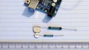
IR optical sensor for occupancy detection
(Sep 2014) There are several ways to detect trains on the track. Most used is ‘current sensing’, whereby a current larger than a few mA drawn from the rails is detected. A special kind of S88, that has the current sensing circuitry on board, is available for this purpose.
The other type of S88 board, often called ‘ground input’, has simple digital inputs that we need to switch to GND. For this we can use a (reed) switch or a transistor whos collector is connected to Vcc via a pull up resistor and that pulls the input to GND when it draws a current.
 If we use the Arduino to simulate an S88 board it will have these ‘simple’ inputs, unless we add current measurement circuitry ourselves, which I do not plan to do. So … I plan to use ether reed switches that are switched by a magnet glued under the train, or IR optical sensors.
 I did some tests with the TCRT5000. Price is not an issue with those … they set you back some €0,16 a piece. The schematics are shown in the image below. All that is needed is a resistor to feed the IR emitter LED. I use 390 ohm, which results in a 10mA current through the LED. The collector of the optical transistor can be directly connected to an Arduino input. No need for an external pull up resistor, we make use the internal Arduino pull up resistors, keeping the circuit as simple as possible.
 There is a drawback using these sensors … they are easily influenced by daylight. If your model train layout is going to be near a window and will catch quite some direct light, chances are your sensors will be constantly ‘on’. There is a way to avoid that, which is to use a 38kHz square wave for your LED power (using an NE555 timer circuit) and use a 38kHz IR receiver (like e.g. the TSOP4038). Drawbacks are that this requires extra circuitry and that the sensors are more expensive.
A video is avaliable on this blog post.
 Train detection with a reed switch and a magnet

(Sep 2014) See this blog post for a video on the use of reed switch and magnets for train detection. In that video the reed switch was a large one of 25mm. The magnets were quite large too. In the mean time that has been changed. I plan to use a smaller reed of 14x2mm, and also smaller magnets with a size of 8×1.5 mm. It has been tested and all works fine, be it that on some ‘high on their wheels’ wagons two magnets, on top of each other, need to be used to get a bit closer to the reed and to increase the magnetic strength.
These are the magnets, acquired at Aliexpress.
Electrofrog
(Aug 2014) I plan to use Peco HO 75 for my track. With this brand there is the choice to use junctions with or without electrofrog. There is a whole lot to be read on the subject on the internet. It seems that in many cases insulated frog does well … but still there may be some loco’s that might stutter or even halt on those when driving at low speeds.
At the club we use electrofrogs, with frog polarity switching. But that involves aditional switch hardware which not only complicates matters but also makes things more expensive. I read that using electrofrog junctions without the additional switching electronics might work fine … the only risk being a possible shortcut of (too) thick loco wheels at the points. Peco seems to have quite a large gap there … I am going to give it a try. Can always go to switched frog if I run into trouble.
So … for now the choice is electrofrog, used ‘out of the box’ without polarity switching.
The best info I came across on the subject is from this website. The image comes from that wedsite.

Possible ways to fix track
(Aug 2014) I’m on the lookout for an alternative for glue. Glue is such a definitive method, while chances are that I want to change my layout a few times. Here’s a little personal brainstorm on possible alternatives, in order of how nice I think the solution:
- Push pins – Could very well be a nice temporary way of fixating, during track laying. Not a definitive solution … it does not look good!
- Thin iron wire – drill 2 holes alongside a sleeper and fix the sleeper with a thin iron wire that is twisted under the plate. Needs to be painted. The plus is, there’s no need for holes in the sleepers, they stay intact! Another plus is, if there is an extra, possibly soft, top layer for sound damping, this just goes through, where nails and screws may not fix good enough if not long enough.
- Screws – Drill a tiny hole in a sleeper and use very thin screws. Alternative, use a small plate between 2 sleepers and fix that plate. Then the screw can be a bit larger and also there is no need for holes in the sleepers. Or, use a scew with a large enough head to cover two sleepers. But … both alternatives will look worse. Also, possibly screws can not be obtained in black, then they need to be painted.
- Nails – Drill a tiny hole in a sleeper and use black nails. Personally … I do not like to nail, they need to go to the very end to fixate and then it is difficult to remove them later.
- Sticky foam tape – Does that hold on the wood? Will need a fill in between to bridge the thickness of the tape.
- Staples – If long enough and strong enough, this could work. Need to be painted. not sure if it will look good, my guess is not.
In the mean time I decided for the ‘thin iron wire’ method. See this post for more details and images.

Hello, Rudy!
I have a DR5000 command station and I must say, your videos about it are a real blessing. Though, I am reaching to you with a problem: I would like to have my dr5000 connected to my home network via ethernet and use de Z21 app on my phone and tablet while being connected to my home network wi-fi. I don’t want to have to disconnect my devices from my home wi fi network and switch to the dr5000’s wi fi. Remaining connected to my home wi fi would also maintain the internet access. So it would be great if you would answer with a small tutorial that takes us through the process. I searched the whole net and didn’t find something comprehensive for beginners. Thanks for the great work you do!
LikeLike
Posted by Radu IP | March 1, 2022, 20:00Well, I’m not sure if what you like to accomplish is possible. The DR5000 has its own wifi server on board and it is the DR5000 named wifi you have to connect to with your phone or tablet.
LikeLike
Posted by RudyB | March 1, 2022, 21:03when i run ARCOMORA install i get error code 1720
steve
LikeLike
Posted by steve | November 30, 2020, 22:18Best post a message or send an email to the arcomora site.
LikeLike
Posted by RudyB | November 30, 2020, 22:44Hi Rudy
I notice that you have both the ECOS command station and the DR5000 command station. Are you using them both together on your layout? If so how are they both being used? I’m planning new computer controlled layout and trying to decide which command station to use – either the ECOS or the DR5000. I’m a little confused about why you appear to have both. What do you see as the advantages and disadvantages of both units?
Bob
LikeLike
Posted by Bob Fuller | November 30, 2019, 08:23I bought the ECoS in a period when the DR5000 was not yet available. If I would have to choose now for PC control I’d always go with the DR5000 for its great connectivity and its unbeatable price. The ECoS is great if you plan to control your layout without a computer.
LikeLike
Posted by RudyB | November 30, 2019, 08:42Hello, Rudy. I am a follower of your blogs and run my layout using Train Controller which you address quite frequently. I thank you for your great videos and learning experiences. In reference to your first post above (9.2014) regarding IR sensors for occupancy detection, I was wondering if you have any guidance as to how to not just detect train occupancy but to be able to detect individual cars as well.
I have experimented for some time trying to achieve an acceptable level of reliability and accuracy using reflective mode IR detection (across the track detection not only disturbs the nearby prototypical scenery but interruption of an IR beam by a variety of individual car shapes and dimension presents its own set of problems) in order to fully automate uncoupling and coupling of cars using Train Controller. I wonder if you might have some insight as to the best geometry and IR devices to use to ensure that each passing car exposes sufficient reflective surface area to be detected while at the same time having a narrow enough beam width to distinguish the space between each car. Once that can be accomplished the rest is a piece of cake with Train Controller to count cars, determine where to stop over the uncoupler magnet, and perform the “Kadee shuffle” to perform the uncoupling action.
Your consideration is appreciated. Thank you.
LikeLike
Posted by Geoff | January 31, 2019, 03:06Hi Ruud,
i am also changing over from analogue ti digital. I have an Ecos 52000 and I intend to use Traincontroller Gold a computer system. I want to make blocks in Traincontroller with one Reed switch pulse system as you use in your video’s. I have question about the lay-out of the tracks. Do I have to make physical blocks in the hardware track lay-0out as well or can the system with blocks with one Reed switch work if the tracks are all connected and physically not separated in blocks.
Awaiting your answer, with Kind Regards, Jan
LikeLike
Posted by Jan van der Schaft | March 16, 2017, 19:33Jan, one of the advantages of using reed switches is that you do not have to separate your track into different electrical sections (as you would heed to do with current setection). Only at the location of the inner rails of the points, the frog, you need isolator connectors to avoid a closed circuit. Take care that for blocks where trains drive in two directions you need a reed at both ends.
LikeLike
Posted by RudyB | March 16, 2017, 21:55Rudy
Thank you very much for your informative videos on TrainController. Excellent work. I am new to to this level of DCC operation. However, I have an ECoS 50200 where I use routes etc controlling turnouts and signals. I want to start using occupancy detectors and came across your video on using Arduino computers as S88 modules. As our layout is completely built would it be possible to use current detection to activate the block instead of reed switches or opto sensors which would be too obtrusive and disruptive in 2mm scale?
LikeLike
Posted by Les Waters | June 5, 2017, 17:59That is perfectly possible. To the Arduino it doas not matter what the sensor is, as long as it gets a LOW (GND or 0V) input signal when a sensor is active and is HIGH (5V or floating) when not. This logic can easily be inverted if needed by changing a line of code in the software. What is needed is the electronic circuits that perform the current detection. A train hobby colleague of mine made a DIY package called OKKIE, these can be had for little money (plus shipping costs) here:
https://arcomora.wordpress.com/
Picture of OKKIE: https://forum.beneluxspoor.net/index.php/topic,74161.0.html
LikeLike
Posted by RudyB | June 6, 2017, 08:21Hi Rudy
My name is Paul Lancaster, and I live in Dundee Scotland. Thanks so much for sharing your information and sketches.
I have used your sketches and managed to produce a working accy decoder, and even a traverser.
I am now starting to convert my pointwork over to servos and have a question regarding your RB_DCC_Decoder_Servo.ino sketch.
To overcome the twitching on startup, I am intending to use a MOSFET (IRLZ44N) connected to pin 13, to allow upto 10 servos be used.
My question is, do I need to define an output pin, and if so what value can be used other than 3 to 13 (3 to 12 are for the servos, and 13 will drive the FET). If not I may have to reduce the number of servos.
Your help and advice would be greatly appreciated.
Thanks
Paul
LikeLike
Posted by Paul Lancaster | December 29, 2016, 22:18Paul, I’m not quite sure how you want to use a FET to avoid the start up jitter? Maybe if you can explain a bit more I can give a better answer? Anyhow … you can use all I/O pins, 0-13 and also A0-A5 (14-19) as outputs. Except 2, which is the input of the DCC signal. Max 10 servo’s can be attached, which is a limitation in the servo library. They need not be attached to the Arduino PWM pins, a servo can be attached to any output.
LikeLike
Posted by RudyB | December 30, 2016, 09:27Hi Ruud
I intend to place the between the Common Gnd terminal of the servos and the Gnd for the board. Then connect the gate to an arduino output. At the end of the setup routine (after the for loop that sets the servos to thier off position value) turn the output on, which will power on the servos.
I’ve never used an analog port as an output and A0 would be perfect (mind you I’ve only done two sketches so far), how do you achieve this?
Thanks
Paul
LikeLike
Posted by Paul Lancaster | December 30, 2016, 14:16I see. Worth a try to see if there is no jitter when you open the FET. It may be necessary to also open the FET before you close down (can use a DCC accessory output for that) which will prevent jitter at close down,melse there will still be jitter at startup. It will still be necessary to put your servo’s in their initial positions before you close down your layout else they will make a jerk from where they are to their initial position at startup.
LikeLike
Posted by RudyB | December 31, 2016, 07:59Thanks Rudy
A bit more seaching and I’ve found out how to use the Analog pins as digital outputs.
This is my fritzing diagram, using pin14(A0) to trigger the FET gate.
http://platform1mrc.com/edit_post.php?id=21436&post_ip=1
I can’t seem to be able to post pictures so have posted a link.
Thanks again
Paul
LikeLike
Posted by Paul Lancaster | December 31, 2016, 00:07Rudy
Thank you very much for your reply. The OKKIE description is in the Dutch language so I am struggling to understand anything. Also, I cannot see from the photograph how the OKKIE board connects to the Arduino. Having said this I am very grateful for your help.
Regards Les
LikeLike
Posted by Les Waters | June 6, 2017, 12:39Hi Rudy
I have found a Arduine Uno Prototype Board in the UK , when used with the 8 relay board from Arduine it
makes a cheap points solution or 9 red green lights, all using the software on your site,you will also need a
Serial to USB converter also form the site, more than one board can be supplied by the opto
Site unoshopper.co.uk
steve
LikeLike
Posted by steve | November 27, 2016, 11:28Hi Rudy, My name is Stewart McManus and I live in Adelaide, South Australia. I have downloaded your RB-S88 sketch for the Arduino. My problem is that I have a Digitrax Zephyr command station which does not have a digital readout like the ECOS except for a 4 char screen for entering Loco and Accessory addresses. The pin-out is a lot different from the ECOS. Could I send you an e-mail with a diagram of the pin-out and could you possibly help me get the interface working with Digitrax. Any help would be greatly appreciated.
Thank you
Stewart.
LikeLike
Posted by Stewart McManus | August 9, 2016, 18:36The Zephyr does not have an S88 bus. You’ll need to find an S88 / loconet adapter. I think they exist, may need to do some Googling.
LikeLike
Posted by RudyB | August 11, 2016, 12:23For the detection I first used three BMD16N-SD from http://www.floodland.nl/aim/info_bmd16n_sd_en_1.htm . I now am starting to use a bit more electronic hardware which would work fine with the arduino as it just says low or high costing about £1 each from MERG, if you wish I could send you the drawing (sorry don’t know how to insert or email).
As for the frog switch I modify the point thanks to Allen Gartners website http://www.wiringfordcc.com/switches.htm
please note I only came across the websites through my research and have nothing to do with them appart for gaining good information.
Jim
LikeLike
Posted by Jim Hardie | January 29, 2015, 18:49Hi Rudy, came across your site while researching using the Arduino with my Ecos. I moved from reed switches to current detection as my N gauge layout suffered unreliability with the reed switches, tend to use 3 sensors per block. Also converting the electrofrog frogs to frog switching using relay boards (china ebay) controlled by the Arduino. Must say you have given me food for thought thanks
Jim
LikeLike
Posted by Jim Hardie | January 28, 2015, 18:29Hi James. I’m curios how you do the current detection? Is that still coupled to the Arduino? Also curious hoe you do the frog switching, since it may only switch after the servo has mved the fork loose from the rail? Switching too soon or too late will give a short?
LikeLike
Posted by rudyb2014 | January 28, 2015, 23:14Hi Rudy. Thanks for your reply. I have heard of Arduino but it seems to be too much to learn. But should you post any blogs or videos I shall take a look. Who knows you may even make it look easy! Success to you too.
LikeLike
Posted by Kai Grambart | September 28, 2014, 10:34Hello Rudy.
I should introduce myself, my name is Kai Grambart, I am a Canadian living in The Netherlands for the past 20 years. I was a member of MTrack for a while but had to stop due to family commitments. I am close to retirement and starting to get back into the hobby. I just wanted to thank you for posting all this and your videos. I first ran across your you tube videos on the Scarm program and I learned a lot from them. Then I came across this info using Ecos and Rocrail. I myself have Marklin and am switching over to digital, I just bought via Ebay a Ecos 52000 ( it’s waiting at my sister’s in Germany, will pick it up next month) I have also read some and downloaded the Rocrail and used it a bit, so once again your info was helpful. I was wondering if you have plans on which track detection hardware you might be using? I have come across the BMD16N (version 1.2) from Avontuur in Miniatuur at http://www.floodland.nl/aim/index_en.htm. Do you have any information on this or are you planning on making a video on track detection hardware ?
Keep up the great work,
Kai
LikeLike
Posted by Kai Grambart | September 26, 2014, 10:49Hello Kai. Well … it sure sounds like you have nice plans! For detection I plan to use one of the many brands of S88 boards available. I am in the process of doing some test, if it is going to be ‘current detection’ (which is what most people use) or if I’m going for optical detection (IR transmitter and sensor). I just had a bunch of stuff come in from China, an Arduino with several sensors. Testing can start. What I like to try is to see if I can make an S88 device out of the Arduino. Will need to write and test some software for that, not sure if I can get it to work. But if it works, it is a lot cheaper than S88 boards … say $8 against $40. Will of course post here if I can get anything working. Also if not :). Success with your endeavours.
LikeLike
Posted by rudyb2014 | September 26, 2014, 16:40