rudysmodelrailway
Layout Specifications:
Scale: HO = 1:87
Table: 300 x 300 cm, folded dogbone shape
Track: Peco code 75, total length approximately 40 m
Turnouts: 23 x Peco E191/E192, [url=http://railwaybobsmodulebuildingtips.blogspot.nl/2013/01/the-peco-electrofrog-circuitry.html]electrofrog[/url], used without polarity switching
Turnout Operation: [url=https://rudysmodelrailway.wordpress.com/2015/02/27/servo-in-the-vertical-mount-position-video/]‘home made’ servo drive[/url]
Train Control: DCC
Command Station: ESU ECoS 50200 (4A, no additional booster)
DCC Accessory Decoders: [url=https://rudysmodelrailway.wordpress.com/2015/01/25/new-arduino-dcc-servo-and-function-decoder-software/]Arduino with own made software[/url]
Train Detection: [url=https://rudysmodelrailway.wordpress.com/2014/10/11/train-detection-with-a-reed-switch-and-a-magnet/]reed switches on the track and magnets under the trains[/url]
Sensor Feedback: [url=https://rudysmodelrailway.wordpress.com/2014/10/03/arduino-used-as-an-s88-occupancy-detector-board/]S88 via Arduino with own made software[/url]
PC Contro softwarel: [url=https://rudysmodelrailway.wordpress.com/category/traincontroller/]Traincontroller 8 Gold[/url] (Rocrail and Koploper will also be added later, just out of curiosity)
Train CAD software: [url=http://www.scarm.info/index.php]SCARM[/url]
Revision plus Wiring Diagrams January 2015
Well … even the version of December 2014 was not final. While laying track, I figured that I do not really need the turntable. If I have 4 loco’s to pull the cargo trains, I can point 2 of them in one direction and the other 2 in the opposite direction. That way there will always be a loco available to pull trains out of the termminal stations. It will be quite a struggle to get the turntable worked into the table. It would mean sawing a hole … possibly even right through the border between two tables … almost impossible. Maybe later, when I have nothing left to do … 🙂
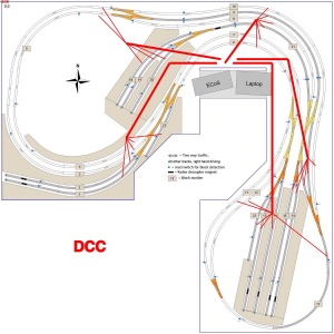
Since track laying is almost coming to its final point, I started looking ahead a bit. An important next step will be wiring. There’s a need for DCC, for S88 sensors and for Junctions wiring. These are the drawings I made to guide the wiring process.
Revision December 2014
 See? The ‘final’ revision of November was not final after all! 🙂 First, I found that I had placed a few points exactly where there are wooden bars under the table, which would make proper installation of the servo’s under the table impossible. The entire junction street of the West station is shifted a few cm South. Luckily that did not cost too much track length of the terminal station tracks.
A more interesting improvement is with the 3 indusrty tracks. It was only possible to do some shunting operations while occupying the main track … not nice. In this latest revision, the 3 industry tracks are connected to the track that comes from station South. That is a long enough track to hold a complete train length. This way it is possible to prepare cargo trains with different (sequence of) wagons via some manual shunting, while at the same time the main track is still running automated train traffic. Much nicer!
The SCARM layout is available for download via this link.
Revision November 2014
 The layout has undergone some final (well … never say final 🙂 changes. The most visible of which is a turntable. Also the double track at the left of the South single track has been made some longer, because the simulation showed that a loco with 3 long passenger cars would not fir there. Now it will. Alao details of the occupancy detector numbers, junction numbers and block numbers are added to facilitate build up of the configuration in the PC control software (probably Koploper and maybe also RocRail).
Original version October 2014
For reasons stated in this post, I’m considering to skip the ‘Phase 2’ I had originally planned, but in stead start with ‘Phase 3’ immediately.
The initial ‘Phase 3’ design has undergone a whole range of revisions. The pictures below show a summary of the evolution. Eventually I ended up with this layout. Maybe not yet 100% definitive … but close.
 If you think ‘he just threw all the track he had room for on the table’ … then, well … you might be right 🙂 I did read several articles on layout design. About time periods, about setting goals for your layout, about the design of a shunting area … and what not. Probably I’m not a ‘typical model railway hobbyist’. To me it need not simulate real world or be ‘prototypical’. My main interest is on the electronics and the computer control. That is what this layout caters for.
- There’s a main loop to ‘circle around’ and there are two terminal stations.
- There are three places that can store loco’s to change direction at the terminal stations.
- Most part is dual track, with traffic driving right hand side.
- There’s also a single track to keep things interesting control wise.
- There’s also a stretch of triple track, with two way traffic on the middle track.
- Every track can be reached from every other track.
- The plan is to have, say, 6 trains and 3 extra loco’s on the layout.
- Maximum train length is 120 cm.
- Minimum curve radius is 50 cm.
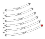
- Track distances: 60, 55, 50 mm (see images below).
 A test in the EEP simulator showed that indeed a 50 mm track space with a 50 cm radius is too tight. There is a website called morop.eu that has gathered or created a whole lot of standards and norms. They have a norm for track distances. They suggest 60 mm for a 50 cm radius and about 55 mm for 550 cm. That is how the layout is now planned.
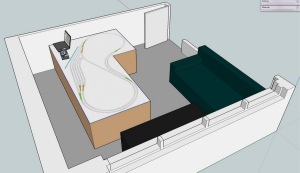
Some 3D views: (The software used to create the layouts is SCARM)
July 2014 – Initial layout plans
These are the layouts I currently have planned. See this blog post for a bit more background info.
The software used to create the layouts is SCARM, a free program. The 3D view is done with Sketchup, also free.


Hi Rudy,
Can I ask how you managed to get the SCARM layout drawing onto the table top in your Sketchup 3D drawing? I have the free web version of Sketchup but cannot see how to import a drawing.
Thanks
Bob
LikeLike
Posted by Bob Fuller | November 29, 2019, 17:37It’s a while ago, I don’t remember exactly the menu used. It is possible to apply an image to a surface to use that as the skin. It is a technique often used to create buildings. I think it is best to Google some, should be possible to find, I bet that is how I found it too. 🙂
LikeLike
Posted by RudyB | November 29, 2019, 18:35Ah, yes, I found it. Here’s a link for anyone else who wants to know how to do it. https://forums.sketchup.com/t/import-images-into-sketchup-free/56540
Thanks Rudy.
LikeLike
Posted by Bob Fuller | November 29, 2019, 21:36Hello;
I am interested in your layout but the scarm file link does not seem to be working.
Nice job!
LikeLike
Posted by Kevin White | December 5, 2016, 05:28