The Traincontroller 9 User Manual, on page 128, says : “Traincontroller Gold provides the possibility to perform all speed measurements with third party measurement facilities …”. Also with Koploper and iTrain this is possible … the speed table can be manually edited.
Of course I wanted to try this out. The only thing is … I do not own a speed measurement device. Of course there always is the option to purchase one, but I thought it much more fun to build one. And … as a bonus … that drops the price considerably.
This is part 1 of 3 on a € 6,- DIY model train speed measurement device.
Part 1: The hardware
Part 2: The Arduino software
Part 3: Speed profiling an engine in Traincontroller 9 with an external device
A speed measurement device not only shortens the time needed for engine calibration in Traincontroller or Koploper or iTrain, it also comes in handy when tuning decoder CV’s like CV2 (low speed), CV5 (max speed) and CV6 (medium speed). And besides all that … it can just be fun to position it somewhere along the track and see the local train speeds.
Images can be clicked to enlarge.
 We’re going to measure travel time between two IR light beams, 200 mm apart. The Transmitters and Receivers are placed alongside a straight track. When a train triggers the first beam, a timer is started. When the second beam is triggered, the timer is read out with microsecond accuracy and, taking the model scale into account (selectable: O, OO, HO, TT, N), the real world train speed is calculated and displayed.
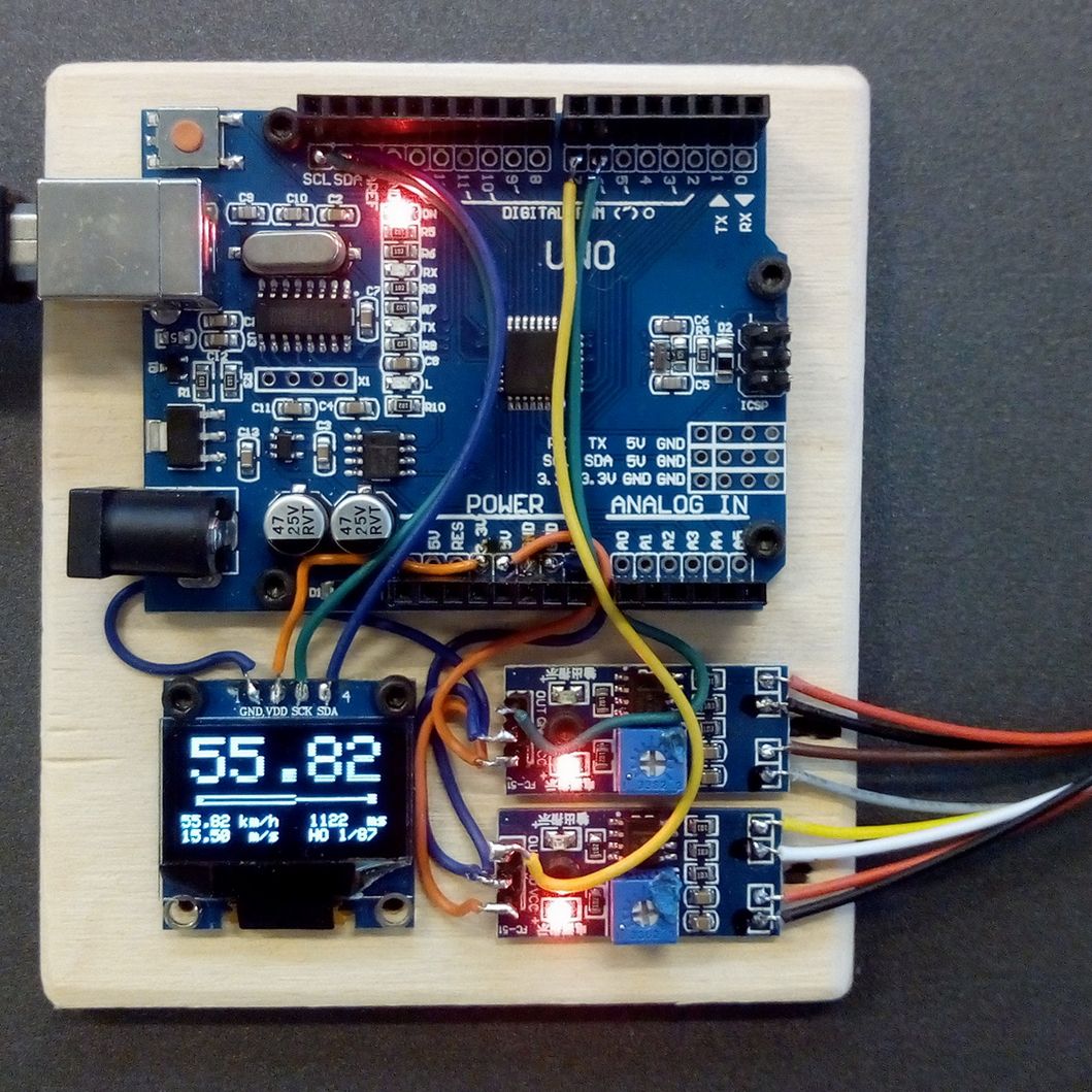 Components needed are an Arduino, two IR sensors and a display. They are mounted on a wooden ground plate. These parts can be acquired at Aliexpress for a total amount of around € 6,-.
LINKS: Arduino Uno / IR sensor / SSD1306 OLED 128×64
The display is optional, but it is fun to have and it eliminates the need to always have a laptop nearby to display the measurement values.
Electrical connections to be made:
Arduino 5V — Sensor1,2 5V
Arduino 3.3V — Display VDD
Arduino GND — Display GND, Sensor1,2 GND
Arduino SCL — Display SCK
Arduino SDA — Display SDA
Arduino pin6 — Sensor1 out
Arduino pin7 — Sensor2 out
 The IR Transmitters and Receivers are cut off from the PCB … we’re going to put them on wires. Make sure to remember which is where and which leads are left and right. To avoid mistakes, I used a marker pen before cutting them off. Solder four wires of about 40 cm length onto a Transmitter and a Receiver. Use wires of 60 cm for the other ones. Solder the eight wires onto the PCB.
I used a connector in between. This is optional, it eases transport and storage. I had one lying around, but if you don’t have one, the male pins that came with the Arduino can be used, combined with a female counterpart that can be acquired here.


 Prepare two wooden bars of 12 x 20 x 240 mm. Drill two 5 mm holes in each, 200 mm apart. Push the Transmitters into the holes of one bar and push the Receivers into the other bar.
 For protection I glued a piece of wood with a cavity over the Transmitters and Receivers. I used plastic tubes to guide the wires along the bar, but this can be done any other way you might prefer.
 It’s time to test the sensors. Power the Arduino up. The power LEDs on the sensor PCBs should light up. Position the Receiver bar such that the IR Transmitters are not seen yet. Turn the potmeters to the point where the LEDs are on the edge of switching on from background light; then turn back a bit, such that the LEDs are off again. Now place the Transmitter bar and the Receiver bar opposite each other, about 5 cm apart. Both sensor LEDs should now be on. Fine tune the potmeters such that the sensor LEDs go off; then turn back a bit to have it on again. Now when you run your finger through the IR beams, you should see the sensor LEDs switch off and on. It’s working!
 To improve measurement accuracy I added a 3 mm plate with two 1 mm holes, exactly 200 mm apart. It is glued onto the bar with the IR transmitters. (In hindsight I realized it would probably be even better to have it on the Receiver side.) I used a laser cutter, which gave me perfect accuracy, but the holes can be drilled by hand, after which their distance can be measured and can be entered in the software. After placing it, I tuned the potmeters again such that both sensor LEDs are on, but are on the verge of off.
 To do measurements, the bars are placed alongside the track. I used a plastic tube to guide the wires over the track such that the engine can pass underneath. The tube is removable for easy transport and storage.
Done … the hardware is ready. Next: Part 2: the Arduino software.

Hallo Rudy,
ik heb het gebouwd met de onderdelen uit je tutorial, maar nu blijven de leds van de sensor PCB’s branden, hoe ik ook de potmeters instel. Ik heb ook al een sensor-PCB vervangen om te kijken of er een fout in zit.
De bedrading heb ik al tig-keer nagelopen.
Enig idee wat hier fout gaat?
Groetjes, Theo
LikeLike
Posted by Theo van Holten | November 25, 2019, 14:24Dat klopt, als alles goed is moeten de leds ook branden, althans als er geen trein tussen staat. Je moet de potmeters afstellen met een trein in de lichtsluis, draaien tot ie net aan gaat en dan ietsje terug tot ie uit gaat.
LikeLike
Posted by RudyB | November 25, 2019, 14:46Hoi Rudy,
bedankt voor je snelle antwoord.
Je aanwijzingen in de antwoord opgevolgd maar nog steeds blijven de led branden.
Er staat spanning op de ir leds ( 1,25V – 1,32V) als ook op de sensors ( 4,8V).
Ik kan met de telefooncamera zien dat de ir leds zwakjes branden (roze kleur licht).
Als de tv remote gebruik dan zie een fel rood licht in de camera.
Ik zie dat op de Arduino de L-led knippert. Heeft dat invloed?
Ik hoopte dat zo’n eenvoudig schakelingetje ook eenvoudig bij mij zou werken ;).
Zijn er nog opties?
Groetjes, Theo
LikeLike
Posted by Theo van Holten | November 26, 2019, 09:07Thanks Rudy for another arduino project. Just finished and it works just fine.
I plan to use it for koploper.
Very wel explained step for step.
Greetings.
LikeLike
Posted by Rob vd Heuvel | June 14, 2018, 16:38Hello Rudy. This is a very practical solution. Can it also be used with Traincontroller 8 Gold? From the foto’s I suppose no external power is needed, just the power of the USB connection, is that correct? The links to Aliexpress show a lot of different models/manufacurers/vendors: how to choose one? Do you have a preferred vendor or manufacturer? Thanks, Bert.
LikeLike
Posted by Bert Caus | March 29, 2018, 15:22TC 8 does not have the option to enter measured speed values, this is new in TC 9. The Arduino needs power from either USB or 7.5 – 12 V on the power jack. To select a supplier I always sort on number of orders, that mostly gives me reliable ones with a good price.
LikeLike
Posted by RudyB | March 29, 2018, 15:45