A ‘reversing loop’ is a quite common feature in a model railway. What needs to be accomplished is to first switch the DCC-A and -B track power in the loop to the same polarity as the track where the train comes from … and later to switch it to the polarity of the track where it heads towards.
With a simple loop to and from the same turnout this can be done by switching 2 relays simultaneously with the turnout. With a less obvious ‘loop’ between two turnouts, like a diagonal connection inside an oval or a Y shape, it becomes less obvious when to reverse A and B. A method that always works is to use 4 sensors to monitor where the train is and switch the relays accordingly.
How it works
When a train enters the loop, sensor S1 detects it and the Arduino switches the relays such that inner rail = A and outer rail = B. Before the train leaves the loop, it reaches sensor S4 and the relays are switched to inner rail = B and outer rail = A. If the train enters the loop from the other side, the relays are switched via S3 and S2. Any kind of sensor can be used: current sensing, reed switches, optical sensors, or other.
(Click the image to enlarge.)

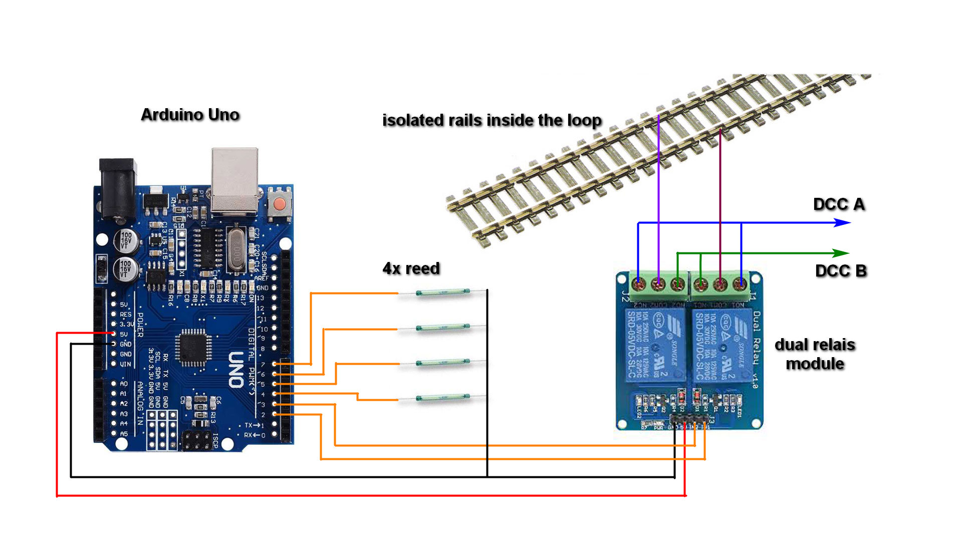
The hardware and wiring
The logic needed could be built with some transistors and resistors soldered onto a PCB. I prefer to use an Arduino though, because it’s almost no work to put together, it’s cheap, it looks quite neat, and because the logic now is in the software, which is super flexible in case you like to add or change something.
What we need is an Arduino Uno, a dual relay module and 4 sensors (I prefer reeds but any other sensor will do). Total costs for a reversing loop: around €5,-. It is perfectly possible to control more than one loop with the same Arduino, max 4 with high impedance or reed sensors (the S1,2 and S3,4 wires can be combined), max 2 otherwise. Just add the extra sensors and relays and add the code to control them.
(Click the image to enlarge.)
The code
Apart from the I/O declarations it’s just 2 lines of code. Is it realiy that simple? Yes, it’s amazingly simple: read the sensors and switch the relays is all that needs to be done.
Note1: The software assumes the sensors are open / high impedance when not activated, which is why the inputs are declared with an internal pull up resistor (INPUT_PULLUP). If your sensors have a hard 0V – 5V output, change the INPUT_PULLUP into INPUT (without pullup).
Note2: The software assumes sensors that are LOW when activated. If your sensors are HIGH when activated, delete the ‘!’ exclamation marks in the ‘!digitalRead(n)’ instructions.
// Ruud Boer, October 2018
// Control for Model Railway Reversing Loop
// 4 sensors are read, 2 relais switch the rails to DCC A/B or B/A

void setup() {
  pinMode(2,OUTPUT); // relay 1
  pinMode(3,OUTPUT); // relay 2
  pinMode(4,INPUT_PULLUP); // sensor 1
  pinMode(5,INPUT_PULLUP); // sensor 2
  pinMode(6,INPUT_PULLUP); // sensor 3
  pinMode(7,INPUT_PULLUP); // sensor 4
}

void loop() {
  if (!digitalRead(4) || !digitalRead(5)) {digitalWrite (2, LOW); digitalWrite (3, LOW);}
  if (!digitalRead(6) || !digitalRead(7)) {digitalWrite (2, HIGH); digitalWrite (3, HIGH);}
}
It works!
The video shows how the relays switch twice, when the train passes by while running inside the loop.
…

Hi Ruud
Do you have any suggestions regarding the distances between sensors and isolator cuts and switch?
LikeLike
Posted by Gareth McNaughton | April 6, 2022, 13:19Switching the relay is instantaneous after triggering the sensor, with all 6 of the reversing loops I built into layouts so far 10 – 20 cm distance between sensor and insulators has proven to work well. Distace to a turnout is not an important parameter, if there is enough room I’d say also there 10 – 20 cm will do fine but if you have less space, it can be as close as you need it to be.
LikeLike
Posted by RudyB | April 6, 2022, 13:25Hi Rudy
Many thanks for the feedback. Now to put into practice.
Gareth
LikeLike
Posted by gareth | April 6, 2022, 13:30Great article, well explained, thank you! How would I use this solution with Occupancy detection using DR4088LN CS ?
LikeLike
Posted by Adam Eddy | May 26, 2021, 10:41If you can get a 5V HIGH and a 0V LOW signal out of it, just connect those to the reversi g loop Srduijo as the sensor inputs. Maybe you need to reverse the signal in the if statement.
LikeLike
Posted by RudyB | May 28, 2021, 15:06This is brilliant!
I’ve never done any sort of programming before or used an Arduino and I hadn’t heard of reed switches. I followed all Rudy’s advice in this article and it worked perfectly. I did originally fit the reed switches perpendicular to the rails as it seemed neater but sure enough, they were less reliable so I now have them parallel. I have double track so I have 2 reverse loops, I copied and pasted the code, adapting it for 8 pins on the Arduino using 4 relays. Very straight forward.
Some experience I can share – if you are using the DR5000 and DR5033 boosters – switch off auto polarity in CV3 – it gets really confusing!
I think this is a great starter project for someone who has no experience programming off the shelf micro controllers like an Arduino.
Thanks for sharing your expert knowledge Rudy!
LikeLike
Posted by ready Eddy | July 19, 2021, 21:05De relais schakelen nu. Ik gebruik op de DR4018 preset 1
16x continue aan/uit schakelaar. Is dit de goede preset?
Ik heb getest en bij het schakelen van alle 2 de modules
wordt idd de polariteit gedraaid. Als 1 module aan staat
en de andere uit (dus ongelijke stand) dan is er geen
spanning op de keerlus. Klopt dit?
Alvast bedankt.
Wil
LikeLike
Posted by Wil | March 25, 2021, 14:28Wil, had ik dit bericht niet al een keer eerder gezien, en beantwoord?
LikeLike
Posted by RudyB | March 25, 2021, 16:17Hallo Ruud
Bedankt voor je reactie. Ik heb dit berichten idd al
eens eerder gestuurd maar ik heb geen reactie gezien.
Je hulp wordt op prijs gesteld
Alvast bedankt
Wil
LikeLike
Posted by Wil | March 25, 2021, 16:35Of het de goede instellingen zijn voor de 4018 weet ik niet, ik ken / gebruik deze units zelf niet. Maar als de relais schakelen dan lijkt het OK. De relais schakelen altijd alle twee tegelijk, zodat de spanning op de rails AB is of BA. Als je (expres) de relais verschillend schakelt dan is de spanning op de rails AA of BB en meet je inderdaad niks.
LikeLike
Posted by RudyB | March 25, 2021, 17:07Hallo Ruud,
Ik doe het in het nederlands mijn engels is niet geweldig.
Geweldig project weer Ruud!
Ik gebruik stroomdetectie en Traincontroller Gold. Is het
ook mogelijk om dit software matig in Traincontroller de polariteit
van de keerlus te regelen.
Als een trein een sensor triggerd is het dan mogelijk om in
een bepaald block of sectie van de baan de polariteit om te draaien?
Ik dacht zoiets eens gezien te hebben in TC.
Ik hoor het graag
Alvast bedankt.
Wil
LikeLike
Posted by Wil van der Wee | February 28, 2021, 12:39Ja, je kan in Traincontroller de inrij sensor uitlezen en in de Operations tab zet je een DCC adres dat je schakelt om het relais te bedienen. Bij de uitrij sensor hetzelfde. Als de keerlus in twee richtingen bereden wordt, dan heb je 4 sensors nodig.
LikeLike
Posted by RudyB | February 28, 2021, 12:48Bedankt voor je antwoord. Heb ik in dat geval ook een Arduino nodig?
Zo ja hoe configureer je deze in TC. Als je alleen de relais nodig hebt
hoe configureer je deze in TC adres etc.
Alvast bedankt
Wil
LikeLike
Posted by Wil van der Wee | February 28, 2021, 19:25Traincontroller kan accessoires schakelen via een DCC adres, Ik neem aan dat je al een of meer DCC decoders in gebruik hebt om bijvoorbeeld wissels te schakelen? Zo ja, gebruik deze dan om een relais te schakelen. Zo nee, dan kan je bijvoorbeeld een Arduino DCC decoder gebruiken, kijk op http://www.arcomora.nl. In de MARDEC /DCCNext handleiding staan voorbeelden voor het gebruik van relais modules, of FET modules waarmee je een relais kunt aansturen.
In Traincontroller kan je de instructie om een DCC adres te schakelen zetten in de Operations tab van de sensor.
LikeLike
Posted by RudyB | February 28, 2021, 20:27Bedankt voor je antwoord. Kun je de relais direct in TC configureren
of heb ik dan toch nog een Arduino nodig? Zo ja hoe koppel je de Arduino
dan met TC. Als je de relais direct kunt koppelen met TC hoe doe je dat dan
adres etc.
Alvast bedankt.
Wil
LikeLike
Posted by Wil van der Wee | February 28, 2021, 20:07Ik heb een DR4018 wisseldecoder. Kan ik daar het relais mee schakelen? Ik zie in je video dat je 4 kanaal relais
module hebt aangesloten op het schema staat een 2 kanaal relais. Kun je ook bij 4 sensors 2 x 2kanaal gebruiken?
Alvast bedankt
Wil
LikeLike
Posted by Wil van der Wee | February 28, 2021, 20:36De DR4018 is een 16 kanaal schakeldecoder, daar kan je wel een relaimodule mee schakelen. Hangt van de relais module af hoe je ze op elkaar moet aansluiten. Er zijn twee relais nodig, beide rails moeten omgeschakled worden. “Kun je ook bij 4 sensors 2 x 2kanaal gebruiken?” … ik weet niet wat je bedoelt met deze vraag.
LikeLike
Posted by RudyB | March 2, 2021, 14:26Ik gebruik DR4018 voor het schakelen van de wissels. Kun je hiermee ook de relais schakelen?
Ik zag in je video dat je een 4 kanaal relais gebruikt in het schema wordt een 2 kanaal relais gebruikt.
Als je 4 sensoren gebruikt heb je dan een 4 kanaal realis nodig? Kun je dan in dat geval ook 2 x 2 kanaal
gebruiken?
Alvast bedankt
Wil
LikeLike
Posted by Wil van der Wee | February 28, 2021, 20:56Bedankt voor het antwoord. De module is 5 VDC betekent dat dan
dat je de module alleen met 5 volt mag voeden. Als dat zo is
en ik gebruik de DR4018 dan heb ik dus een andere module nodig
met een hoger voltage. Is dat correct?
Bij voorbaat dank,
Wil
LikeLike
Posted by Wil | March 5, 2021, 10:01In de DR4018 handleiding is niet duidelijk he zijn uitgangen schakelen, maar ik vermoed dat het een uitgangestransistor naar GND is. Je kunt de 12V voeding niet gebruiken op e 5V relais module, maar je kunt wel het volgende proberen:
1. Sluit de GND van de relais module aan op de GND van de DR4018 voeding … er van uitgaande dat je die met een gelijkspanning voedt, niet met een trafo.
2. Sluit een weerstand van zeg 1 kohm aan op de 5V en de andere kant op de ingang van de relais module.
3. Sluit een draad aan van de ingang relais module (en weerstand) naar een uitgang van de DR4018.
4. De DR4018 kan nu het relais schakelen.
Voor de zekerheid kan je het met een multimeter eerst even nameten, aan de weerstand, zonder de relais module aan te sluiten … hij moet schakelen tussen 5V en 0V.
LikeLike
Posted by RudyB | March 5, 2021, 10:30De relais schakelen nu. Ik gebruik op de DR4018 preset 1
16x continue aan/uit schakelaar. Is dit de goede preset?
Ik heb getest en bij het schakelen van alle 2 de modules
wordt idd de polariteit gedraaid. Als 1 module aan staat
en de andere uit (dus ongelijke stand) dan is er geen
spanning op de keerlus. Klopt dit?
Alvast bedankt.
Wil
LikeLike
Posted by Wil | March 15, 2021, 18:42De relais schakelen nu. Ik gebruik op de DR4018 preset 1
16x continue aan/uit schakelaar. Is dit de goede preset?
Ik heb getest en bij het schakelen van alle 2 de modules
wordt idd de polariteit gedraaid. Als 1 module aan staat
en de andere uit (dus ongelijke stand) dan is er geen
spanning op de keerlus. Klopt dit?
Alvast bedankt.
Wil
LikeLike
Posted by Wil | March 14, 2021, 20:23I´m a novice in arduino, so I´m trying new experiences continuosly… I’ve been analyzing your project and haven’t found where the arduino feed comes in. Can you explain where? Tks
LikeLike
Posted by Nilton Torquato | August 24, 2019, 14:47I´m telling about the electrical feeding…. Excuse me for my english, I´m not a native speaking. I´m from Brazil.
LikeLike
Posted by Nilton Torquato | August 24, 2019, 14:50You mean the power supply? That can be accomplished via a DC adapter somewhere between 8 -12V.
LikeLike
Posted by RudyB | August 24, 2019, 16:20What do you mean with the word ‘feed’?
LikeLike
Posted by RudyB | August 24, 2019, 16:18Yes, i was asking about power supply. In your video a coudn’t find the dc power cable in arduino…. tks for the answer.
LikeLike
Posted by Nilton Maurício Martins Torquato | August 24, 2019, 17:06Hi Rudy !!! Great work !!!
I found your project very relevant.
But I would like to implement an automatic servo drive in turnout. It’s possible ? ?
LikeLike
Posted by Demarques Ribeiro da Silva | April 11, 2019, 14:39Of course that is possible. I assume by ‘automatic’ you mean by DCC control? If can wait a couple of weeks, I have planned videos on both a DCC accessory decoder as well as a servo decoder. If you can’t wait, go to rudysmodelrailway.wordpress.com and navigate to the software page, there you candownload a zip file with all knds of Arduino DCC decoders. There’s also a drawing of the hardware you need to connect the DCC to the Arduino. Alternatively you can download software with has added extensive configuration options via the PC from the arcomora.com website.
LikeLike
Posted by RudyB | April 11, 2019, 15:22I appreciate your attention.
Yes I understand a little of the DCC system. And I can wait for whatever is necessary.
I’d like to know how I can leverage your source code and implement the turnout servo drive automatically when I detect the locomotive. Can you develop and send it to me?
Thank you very much
LikeLike
Posted by Demarques Ribeiro da Silva | April 12, 2019, 20:34OK, I understand that you like to switch the turnout based on the train sensor? Most easy is to always rum through the loop in the same direction. In that case you need only two sensors.
SENSOR_A should be placed in front of the turnout that enters the loop. This sensor switches the two relays and sets the turnout to ‘straight’.
if(digitalRead(SENSOR_A) == 0) {
digitalWrite(RELAY_A_PIN, HIGH);
digitalWrite(RELAY_B_PIN, LOW);
setpoint = ANGLE_STRAIGHT;
SENSOR_B is placed in the loop, in front of the turnout where the train leaves the loop. We now need to switch both relays back and set the turnout to ‘bend’.
if(digitalRead(SENSOR_A) == 0) {
digitalWrite(RELAY_A_PIN, LOW);
digitalWrite(RELAY_B_PIN, HIGH);
setpoint = ANGLE_BEND;
That’s all. On how to control the servo with the variable setpoint, see video 18 or 26.
LikeLike
Posted by RudyB | April 15, 2019, 08:46Hi Ruud,
Thanks for sharing your sketch.
I have modified it for use on my lay-out. I intend to use only two (IR) sensors and one DP relay.
When the train passes over one or both of the sensors, the relay will be energized, setting the polarity correct for entrance. When the train is passed, the relay will be down, setting the polarity correct for leaving .
Also i added a delay in order to be shure that a reading error (maybe cuased by a small coupler) will not directly turn down the relay. The period can be adjusted.
A test on the testbench is promising.
Kind regards,
Juroen
// Juroen january 2019
// based on sketch by Ruud Boer, October 2018
// Control for Model Railway Reversing Loop
// 2 sensors are read, 1 DP relay switchews the rails A/B or B/A
long previousMillis = 0;
const unsigned long period = 350; //period during which relay will be up after passing the train, also to compensate for small couplers
void setup() {
pinMode(LED_BUILTIN, OUTPUT);
pinMode(2,OUTPUT); // relay 1 Double pole
pinMode(4,INPUT_PULLUP); // sensor 1 outside of rverse loop
pinMode(5,INPUT_PULLUP); // sensor 2 inside of reverse loop
}
void loop()
{
unsigned long currentMillis = millis();
if (!digitalRead(4) || !digitalRead(5))
{
previousMillis = currentMillis; // Remember the time
digitalWrite (2, LOW);
digitalWrite (LED_BUILTIN, HIGH);
}
else
{
if
(currentMillis – previousMillis >= period)
{
digitalWrite (2, HIGH);
digitalWrite (LED_BUILTIN, LOW);
}
}
}
LikeLike
Posted by Juroen | January 16, 2019, 20:19you can do it like that if you always enter at the same side. The reason I used 4 sensors is to make it work no matter what side you enter and it also works also in case of a power down. At power up, the situation is not clear and when a train is inside the loop and leaves, you can get a short circuit … but not with 4 sensors.
LikeLike
Posted by RudyB | January 16, 2019, 22:08Ruud,
I think it will work in both directions.
The two sensors I use are both at one end of the reverse loop. E.g. in your drawing that would be sensor 1 and sensor 2. If one of them ‘sees’ a train the relay will be energized for entering or leaving the loop at that end.
The relay is normal de-energized. In that situation the polarity is set for leaving/entering the loop on the other side.
That is why I use an if – else statement.
However, if it does not work I will keep you informed!
And thanks again for sharing your experiences on your website.
Regards, Juroen
LikeLike
Posted by Juroen | January 17, 2019, 07:14What if you power on while there already is a train in the loop?
LikeLike
Posted by RudyB | January 17, 2019, 08:04Hi Ruud,
I have also a picture, based on your picture in order to explain how it should work. Currently I see no option to share pictures in this discussion. Is there a way to share the picture with you?
Regards, Juroen
LikeLike
Posted by Juroen | January 17, 2019, 07:40I’m glad that I found your solution. I am curious as to the use of the reed contacts as opposed to IR sensors. How would I place them on my N Scale track and do I have to modify my locos?
LikeLike
Posted by MARK NOACK | November 15, 2018, 20:35The reeds can be placed in two ways:
– horizontal in the direction of travel, maybe need to make a cut in some sleepers to make room such that it slays low enough.
– vertical … just drill a hole, bend one wire 180 degrees and place the reed in the hole.
You’ll need small and strong neomybium magnets, of which plenty sizes and shapes are available at Aliexpress.
LikeLike
Posted by RudyB | November 15, 2018, 21:23Hi Rudy,
I was wondering how this reversing loop control could be adapted for a reversing triangle (which in effect is another form of reversing loop. Your thoughts would be welcomed.
Thanks
Tom
LikeLike
Posted by Tom Busza | November 12, 2018, 13:54Examine your layout closely and mark the junction where the A-rail connects to the B-rail. Go back to the junction where you came from. Mount the the 4 sensors, 2 at each side, on rail in between and all should be well.
LikeLike
Posted by RudyB | November 27, 2018, 10:55Hi Rudy !!! Great work !!!
My mind in going on from your post reading. I think it could be posible to resolve the loop just with two sensors and two relays. I expose this draw https://photos.app.goo.gl/NWWWqAQDrePCSycn7 to share opinions and suggestions. May be some detail has been forgotten by myself.
LikeLike
Posted by Santa Cecilia Término | November 8, 2018, 12:41G’day Rudy,
Yet another Gem!
Many thanks for sharing.
Cheers
Phil
LikeLike
Posted by Phillip | November 3, 2018, 17:39